Currently in Simerics you don't have any control over where the streamlines are released on a body (this is a feature that is on the Simerics development list). Sometimes you can see what you need to by increasing the number of streamlines, but not always.
If you need to see streamlines in a particular place, the process is to create a small surface face in the location of interest and release the streamlines from there (think of it as a dye tap that would be used in a model test).
For example, if you wanted to see streamlines at the location of a bilge keel so that you can properly align it, create a small patch in the hull surface at the forward end of where the bilge keel will go. This is done in Rhino by intersecting a small cylinder roughly perpendicular to the hull, so that there is a circular "patch" in the hull (maybe a few centimeters across). Then delete the cylinder and split the hull surface using the intersection curve. Finally, join the hull and the small patch as part of your closed polysurface.
When setting up the CFD run in Orca3D, create a new Face Type by right-clicking in the Simerics Face Type dialog and selecting Add:
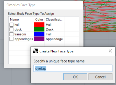
Then during the CFD run or when it is complete, you can turn streamlines on for that face (dyetap). If you have already run the analysis, you will need to re-run it because you now have a new model that includes the dyetap surface.
You do not need to limit yourself to just one of these; you can put in as many as will be necessary to visualize the streamlines that you need to see.