This functionality requires the Premium version of Orca3D Marine CFD (Simerics-MP).
To perform a roll decay analysis you need to start by first creating a standard resistance or self-propelled simulation with Orca3D Marine CFD. There are a few specific things that you need to consider when first creating a simulation that will be used for performing a roll decay analysis.
1(a). Remember to select the option to perform an "asymmetric" analysis since a rolling simulation does not have port/starboard symmetry in the flow field, even if the geometry itself has symmetry.
1(b). Consider adding CFD grid refinement to the simulation, especially around the hull and any appendages that contribute significantly to the roll damping like bilge keels.
1(c). The fluid flow around the body during a roll damping analysis can change quite abruptly as the vessel rolls in one direction then the other. This means that it is recommended to use the "Explicit" VOF solver in SimericsMP. While this can be accomplished manually within the SimericsMP user interface, the explicit solver is also used automatically when the hull type is set to Low-Speed Displacement or Planing. the Low-Speed Displacement hull time has the additional advantage of adding extra grid refinement around the body and the free surface, so it is preferred particularly if you are analyzing a displacement hull.
1(d). Pay attention to the roll moment of inertia. Normally this value is not important for a standard resistance or self-propelled simulation. However, for roll damping simulations it clearly has a significant effect. If you have computed a value for the roll inertia of your vessel, enter that before creating the simulation. Otherwise, the default value (based on rules of thumb) should be reasonably close.
After opening the simulation in SimericsMP, you will want to make additional adjustments to the CFD grid to facilitate the relatively large motion of the vessel during the simulation. To accomplish this, select "Built Meshes" over in the Geometric Entities tree. This automatically shows you the current mesh settings in the Properties panel. As shown below, change the Setup Option to "Advanced Mode," and set the Max Pitch Angle to at least 10 degrees and possibly greater depending on the amount of roll expected. Note that there is no direct setting for Max Roll Angle in the Marine mesh settings. We are using Max Pitch Angle as a surrogate, with the recognition that in an approximate sense the Max Roll Angle will roughly be the Max Pitch Angle * Length / Beam of the vessel. After adjusting Max Pitch Angle, click "Build Marine Mesh" to rebuild the mesh that will be used for the simulation.

If you are simulating roll damping behavior with forward speed, you will need to first run the simulation straight ahead without roll until the simulation reaches a steady state. If you are simulating roll damping at zero speed, you can skip this step and continue with the steps below.

2(c). Next you must remove all of the numerical damping so that it does not artificially affect the dynamic behavior of the vessel. Set all of the numerical damping to zero by selecting each of the dynamics modules and setting the corresponding damping coefficient to zero as shown below for marinePitch (do same for marineHeave and marineRoll). Then save this simulation with a new name.

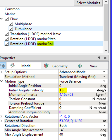
(i) In the first approach, you would load the results from the simulation without roll as the starting point. Then set the initial roll velocity to the desired value such as 15 deg/sec as shown earlier. To make this approach work, you must choose the simulation option "Start from Solution" before clicking the Start button. This sets the simulation time back to zero so that the entered "Initial Angular Velocity" is applied. If you just did a Continuation Run here, there would not be any roll velocity applied.

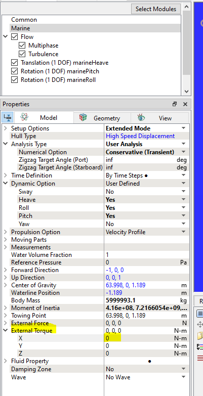
(ii) In the second approach, you load the results from the simulation without roll, but instead you choose "Continuation Run" as the starting condition. In this approach instead of an initial roll velocity you will apply an external roll torque to the model for a specified amount of time. To do this add an expression for the External Torque option in the marine module as shown below. This would be an "X" torque and it would only be applied for a few timesteps before turning it back to zero. In this example the X torque expression might be defined in the Expression Editor as something like:
xTorque = time <= startTime + deltaTime ? rollTorque : 0
where startTime is the beginning time of the continuation run, deltaTime is the amount of time in seconds you want to apply the external torque, and rollTorque is the magnitude of the roll torque in N-m in this case. Click Start to run the roll decay simulation.
(iii) When performing a roll decay with forward speed for a resistance simulation (as opposed to a self-propelled simulation), you will need to manually set the forward speed because the "surge" degree-of-freedom is not a part of the simulation. Instead the vessel forward velocity was prescribed. To set the forward speed, expand the "Propulsion Option" in the Marine module properties, and set the "Velocity Profile" and "Projected Max Velocity" speeds to match the prescribed velocity from the resistance simulation with no roll, as shown below.

In either approach, after choosing the appropriate initial condition, click Start to perform the roll decay simulation.