
The Orca3D MaxVCG analysis can be computationally-intensive because it iterates through VCG values to find the maximum allowable VCG that still satisfies all stability limits in the selected criterion. At the maximum allowable VCG for a given condition(draft/displacement/trim), the margin between the required value and the actual computed value should be at or close to zero for at least one of the stability limits (assuming the ship is statically stable at that condition). For each candidate VCG value, the software performs a full stability evaluation, which may include heeling to port and starboard depending on the Heel Direction input selection. The VCG for the first calculation iteration is chosen based on the user’s input value of Initial VCG. It is recommended that the user choose an Initial VCG that is within the range of expected operating VCG’s for the vessel. This choice can help to accelerate convergence of the iterative solution. In subsequent iterations, the next candidate VCG is chosen based on the vessel’s predicted stability behavior as it relates to the effect of VCG on stability limit margins. The predicted stability behavior is often difficult to estimate accurately because there is a complex relationship between the change in minimum stability limit margin and change in VCG.
In some cases, the user may find that the MaxVCG analysis fails to converge to a solution, or that the solution(s) it finds seems inconsistent. This could happen when the sensitivity of a specific stability limit to a change in VCG is very non-linear. For example, the change in the heel angle at which the maximum righting arm occurs relative to the change in VCG, can be almost flat for a range of heel angles and then rapidly change at specific angle as shown below by the blue curve. This happens even though the maximum righting arm varies smoothly as shown by the green curve.
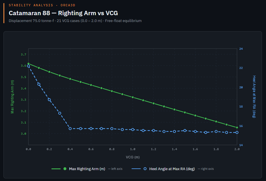
To address the wide variation in vessel geometry that Orca3D may encounter, the MaxVCG analysis allows the user to adjust certain calculation parameters as described below. In some cases, it may be necessary to adjust one or more of these parameters. These adjustments can have a significant input on both the computation time as well as the accuracy of the results.
Maximum VCG Iteration Count
There is a limit on the number of VCG iterations for each input condition to the MaxVCG analysis so that in cases where the behavior is non-convergent, the computation will eventually stop and move to the next condition. This limit is called the Maximum VCG Iteration Count. Recognize that this represents an upper limit, and that in general the solution tolerance should be reached before the iteration limit is reached. Certain vessel geometries exhibit characteristics that cause the iteration solution to converge more slowly. In cases like these, the user can increase the Maximum VCG Iteration Count to allow the computations to continue and hopefully reach convergence. If the result of a MaxVCG analysis shows that convergence was not reached (and that the computation had not stopped either because of a statically unstable condition or because it was not possible to meet all the stability limits in any condition), you can perform the calculation again with a larger iteration limit.
Maximum VCG Solution Tolerance
To determine when convergence has been reached, the MaxVCG analysis relies on a convergence tolerance. When the change in VCG from one iteration to the next is less than this tolerance, it is assumed that the solution has been reached, and the MaxVCG has been found. The default value of this tolerance is 1mm. Increasing the magnitude of this tolerance may allow the calculation to converge more quickly at the expense of some accuracy in the result.
Heel Angle Increment
The default heel angle increment for stability criteria evaluation is 5 degrees. This has been found to be widely applicable in our testing of various vessel types. However, in some cases where the righting arm curve variation has abrupt changes in shape, a finer heel angle increment may be warranted. A typical example of this is a catamaran hull form which tends to have a large initial stability (i.e., GMt) up until the maximum righting arm is reached, after which the righting arm tends to decrease relatively rapidly. If a stability limit is applied that is sensitive to the precise location of the angle of maximum righting arm, it will often be necessary to use a finer heel angle increment (e.g., 1 degree) for the evaluation. The user can override the default increment to better resolve important righting arm features like this. Future versions of Orca3D may include the ability to specify a variable heel angle increment to provide further speed optimization for the MaxVCG analysis. For example, in the case of a catamaran it would be helpful to apply a smaller heel angle increment near the peak of the solution but use the default increment away from the peak.
Max Heeling Angle
In the current implementation, the initial righting arm analysis for each candidate VCG value is computed up to the angle of vanishing stability (GZ0). After performing this initial righting arm calculation, some additional key heel angles are evaluated such as the point at which the maximum righting arm occurs (GZmax) and the point at which downflooding occurs (Flood). Then the applicable stability limits are examined to determine if all the necessary limit parameters can be evaluated. If one or more stability limit parameters cannot be evaluated, then the righting arm calculation continues to an expanded range of heel angles, up to 180 degrees, until all the stability limits can be evaluated.
The MaxVCG analysis allows the user to override the Max Heel Angle used in the initial righting arm calculation. Sometimes, the angle of vanishing stability is well beyond the range of heel angles needed to evaluate the stability limits. If it is known in advance that the limits can be evaluated without reaching the angle of vanishing stability, the user can limit the maximum heel angle to a specified magnitude that is smaller to help to speed up the computations. However, it is important to understand that this heel angle limit is just applied to the initial righting arm calculation described earlier. It is still possible for the calculation to expand the range of heel angles if it is determined that one or more of the required stability limit parameters have not been encountered. This could happen, for example, if one of your stability limits references the downflooding angle, and the downflooding angle has not yet been reached by the max heeling angle input by the user. One potential cause for this is that the downflooding point is defined on say the port side, but the default heeling direction is to starboard. Be sure to account for this either in how you define the downflooding points (both sides) or in which direction you allow the vessel to heel. Future improvements to this implementation are planned that should reduce these issues.